heating up the atmosphere
front image with gases

What is Global Warming?

Why is it warm in a greenhouse on a cool day? The answer is Ultra Violet (UN.). U.V. radiation penetrates the clouds with its medium frequency radiation waves. It can penetrate glass or perspex. Only when the U.V. hits an object, such as a flowerpot in a greenhouse does it turn from medium frequency U.V. to Long Wave Heat Radiation – that’s why it warms up.

In the atmosphere above the Earth there is a layer of naturally occurring gases which act as the glass in a greenhouse trapping heat around the Earth. This layer needs to be d correct thickness to enable life to survive. Gases produced within industry have added to the thickness of this layer of “Greenhouse Gases”. The most notable one being Carbon Dioxide (CO2). Carbon Dioxide is a by-product of burning fossil fuels such as coal and oil in our power stations. There are approx. 7 billion tonnes of CO2 produced each year from creating electricity.

All refrigerant gases (apart from Hydrocarbon’s) are extremely bad greenhouse gases. There are also other gases such as Methane that contribute to “Global Warming”.

The U.V. from the Sun penetrates the Greenhouse Gases within the atmosphere and hit the Earth, The U.V. then changes energy to long wave radiation – heat. This heat cannot escape back through the Greenhouse Gases and we get Global Warming. The thicker the layer of Greenhouse Gases – the warmer the surface of the Earth becomes.

The average temperature around the Earth at present is + I5°C. If there were no Greenhouse Gases the average temperature would be -18°C. We do need some Global Warming to survive- but not too much.

Kyoto Protocol

In 1990 the countries that had signed up to the Montreal protocol held a meeting in Kyoto, Japan and agreed to reduce the emissions of gases with a Global Warming potential to a level of 5% less than the level in 1990. The UK has agreed to achieve a reduction of 12.5% below 1990 levels.

As you can see from the tables above all refrigerants have a global warming potential and/or an Ozone depleting potential, because of this no refrigerants except HC’s can be intentionally released to atmosphere.

INTENTIONAL RELEASE OF REFRIGERANT GASES TO ATMOSPHERE CAN LEAD TO PROSECUTION AND LARGE FINES

How the Ozone layer protects us from U.V.rays

The Ultra Violet Radiation from the Sun hits an Ozone molecule. In doing so it splits the Ozone molecule.

It splits it apart, back to: - 0+02

and stops most of the u.v. reaching us

ozone-molucule-protecting-us

The cycle is then repeated. The energy from the Sun again joins the 0 and 02 to form Ozone 03. So, this is a constant “split” and “rejoin” process. This is our protection against the dangerous Ultra Violet waves

Why is there a hole in the Ozone layer?

If refrigerant gas (CFC) leaks from a system it naturally drops to the ground because it is heavier than air. It gets up to the Stratosphere where the Ozone layer is by attaching itself to dirt,dust and debris and hitches a ride. It takes approx. 7 years for the CFC to reach the Stratosphere. Once the CFC molecule is up there, it is split apart by the U.V. The Chlorine molecule breaks away from the Fluorine and Carbon molecules. This is now called “Free Chlorine”. This Free Chlorine molecule attacks the Ozone and depletes it. It is estimated that one Free Chlorine atom can prevent the formation of 10,000 molecules of Ozone.

CFC refrigerants have a life span of approx. 100 years in the Stratosphere.

world-stratosphere

Ozone Depletion

The Ozone layer starts approx. 10km above the Earth and ends at approx. 50km above the Earth. Within this 40km wide band the scientists have determined there is approx. 95% of our Ozone (the other 5% is just outside this band).

The purpose of this Ozone layer is to protect us from harmful Ultra Violet radiation (U.V.). It acts rather like a shield, protecting humans, plant life and marine life.

In May of 1985, two British scientists discovered a hole in the Ozone layer at the South Pole. The fact is that the hole is now so large, it uncovers parts of Southern Chile. The people there need to take special precautions, as there is no “shield” of Ozone to protect them. They suffer from skin cancers and cataracts.

What is Ozone?

Ozone is a group of 3 Oxygen atoms – when all three join it becomes an Ozone molecule. The chemical symbol for Ozone is 03. Lets start by explaining the “joining” process.

ozone-02

A single Oxygen atom, unstable by itself will automatically join to another Oxygen atom to form 02 – Oxygen.

How is Ozone produced (ON
Another Oxygen atom will not automatically join with two atoms that have previously joined together, it needs some help.

The Sun emits a wide spectrum of magnetic radiation. It emits long wave radiation (heat), medium wave radiation (U.V.) and short wave radiation such as x-rays.

Between long wave and medium wave radiation there is a form of radiation energy, which is needed to create Ozone. This energy helps attach the third Oxygen atom to the two atoms that have previously joined together – to form Ozone.

energy-from-the-sun

An ozone molecule (3 oxygen atoms linked together}

Ozone can only be produced when the Sun is out. That’s why at the end of the Antarctic winter, when there has been no Sun for up to 6 months, no Ozone has been produced and the hole appears. On the other hand, by the end of the Antarctic summer, when the Sun has been out for 24 hours every day for 6 months, the hole fills itself in. The hole has gradually increased in size over the years due to the increase in CFC (Chlorine, Flourine, Carbon) emissions.

The Institute of Refrigeration Codes of Practice

The institute of refrigeration have put in place guidelines on what refrigerant release is permissible under the Montreal and Kyoto agreements, this currently is covered under the Environmental Protection Act 1990, so there will be a specific Refrigerant Handling regulation requiring all people who use refrigerants to be trained and registered. Below are highlights taken from the institute of refrigeration codes of practice that relate to domestic refrigeration servicing. These guides cover all refrigerants except Hydrocarbons (R600a, R290)

Deliberate Venting ·

  • Releasing refrigerant to atmosphere instead of full recovery
  • · Multiple evacuation of systems breaking each vacuum with refrigerant n
  • Using refrigerant to “blow out” blocked or restricted systems ·
  • Adding refrigerant to a known leaking system to help locate a leak ·
  • Release of refrigerant to cool cylinders to aid filling

Inadvertent Loss

  • Small quantities from the normal connection and disconnection of gauge lines. ·
  • Small loss from refrigerant oil after full recovery process has been completed
r600a-removal
r600a-removal-2

Note care must be taken when working with R600a, as it is flammable; please refer to working with flammable refrigerants procedure.

  • Check the area is safe to work in.
  • Access the system (piercing pliers, line tap, schrieder, etc.)
  • Connect up as shown (ensure vent hose goes to clear air)
  • Run the vacuum pump with the tap on the gauge open
  • Keep running the vacuum pump until all refrigerant has been removed
  • Check, both sides of the system (pierce in to high side)
recharging-r600a-system


Note care must be taken when working with R600a, as it is flammable; please refer to working with flammable refrigerants procedure.

  • ·After full evacuation of the system (20mins) ·
  • Disconnect the gauge line from schraeder valve ·
  • Purge the R600a charge line to clear air (eg,outside) not within working environment ·
  • Ensure the gauge line tap is closed then connect to the system ·
  • Place R600a gas bottle on the scales and secure charge line ·
  • Reset the charging scales display to zero ·
  • Open gauge line tap and scales will count down from zero (minus figures) ·
  • Stop when 95% of full charge has been added if carrying out a re-gas ·
  • Stop when 100% of full charge added if compressor changed ·
  • Disconnect and purge charge line to clear air (eg,outside) ·
  • Run and test

    Refrigeration Gauges and Manifold
    Understanding the gauges and the pressures shown on them is essential to correctly diagnose and repair a refrigeration system. The gauges indicate the pressure inside the system. The manifold allows you to add and remove refrigerant from the system and is simply a set of valves and interconnecting pipes.


The gauge measures the pressure of the port directly below it. The valves stop the flow of refrigerant between the outer sections and the centre section. If the valve is opened then refrigerant can flow between these sections.

Low side Low pressures

High side High pressures


Gauge Scales

On the gauges you will find a number of different scales. The main scale we refer to is the pressure scale. This indicates the performance of arefrigerant system. The refrigerant temperature scales show the temperature the refrigerant is operating at inside the system.

refrigerant-scales-temperature
  • Asses the refrigerant type
  • Access the refrigerant system (piercing pliers, line tap valve, schreider valve, etc.)
  • Connect recovery unit to correct recovery cylinder as shown
  • Recovery refrigerant (staying below Zero)
  • Check both sides of system are empty (pierce the high side)
  • Purge unit before storing

Refrigerant systems need to be evacuated to remove air and moisture after service work has been carried out. Moisture will only be removed if a full vacuum is held for a prolonged period of time (20 minutes). The pressure gauge should indicate 28″Hg and this reading should be held when the manifold is closed and the vacuum pump switched off. If the pressure reading rises then this would indicate that the system has a leak. Moisture held within the air left in a refrigerant circuit can effect performance and possibly form acids that will damage the system.

Pressure Scales

There are two main scales commonly used to measure pressure. Pounds per square inch (psi) an imperial measurement which is being replaced by bar. Which is a metric scale for pressure measurement. 1 bar is equal to 14.7 p.s.i. Zero on both scales is atmospheric pressure. Any pressure below atmospheric pressure is referred to as a vacuum, in bar readings a vacuum is indicated by a minus sign before the number and on the p.s.i. scale a vacuum is measured in inches of mercury (“Hg). Some newer gauges may also show a vacuum in millimetres of mercury (mmHg). The Mercury in these measurements refers to the size of the column of Mercury that can be sucked up a tube by this amount of vacuum.

p.s.i x 0.07 = bar
bar x 14.7 = p.s.i.

It is important to always check that your gauges are reading zero before connecting to any system. If your gauges read 5psi when open to atmosphere then 5psi would have to be added to the pressure reading taken from the system. Also before connecting to any system ensure that the valves are closed.

Recovery Cylinder Colour Codes

Never mix refrigerants in the R134a and R22 cylinders R12 Cylinder can have any gas other than R134a & R22.

Never overfill. or over pressurise recovery cylinders

Fault Symptoms

Fault

Symptoms

Gauge

Repair

Com p.
Running

Com p.
Off

Short or under charged with refrigerant

Only partly frozen evaporator Cool condenser Running continuous (possible)

Lower
than

expected

Rises when switched off

Leak test. Remove refrigerant. Repair leak. Change drier Vac. System Recharge System

Leak test
Run test

Over charged

Fully frozen evaporator Suction

pipe frozen outside cabinet Running continuously Comp. Very hot

Higher than

expected

Higher than expected

Remove refrigerant (vent or recover as appropriate) till frost line goes inside cabinet

Leak test
Run test

Poor pumping

compressor      .

Partially frozen evaporator Noisy compressor Running continuously Comp. Very hot

Much higher than expected

Rises very quickly (refrigerant can be heard passing back through comp.)

Recover/vent refrigerant. Change compressor and filter. Vac. System Recharge system

Leak test

Run test

Restricted/partially blocked

Partially frozen evaporator

Lower than

expected

Rises very slowly

Recovery/vent refrigerant. Clear blockage


Cool Condenser


Change drier Vac. System Recharge system

Leak test Run Test

Totally blocked system

No cooling

Very deep vacuum

No change

Recovery/vent refrigerant. Clear blockage Change drier Vac. System Recharge system Leak test Run Test

R600a Typical Gauge Readings

normal running cold cabinet
poor pumping compressor
completely blocked system
loss of refrigeration partial restriction
normal running room temperature r134a
completely blocked system r134a

Why use refrigeration? We use refrigeration to extend the storage times of food, by lowering the temperature we slow down both bacteria and enzyme growth.

How does a fridge cool the food., Fridges work by moving heat from the inside of the cabinet to the outside.

So how do they move the heat?

Most modern refrigeration systems work on the same principle, of using a refrigerant that has a very low boiling point (R134a boils at -26°C), and forcing the refrigerant to constantly change state from a liquid to a vapour and back again.

When a liquid evaporates and changes into a vapour It will absorb heat When a vapour changes into a liquid It will give off heat To force the change in state we change the pressure Lowering the pressure lowers the boiling point Raising the pressure raises the boiling point

If the process of increasing and decreasing the pressure or the dissipating and
absorbing of heat are disrupted then the refrigeration process will be affected.

Examples:

Dirty/blocked condensers stop the heat from being dissipated.

Iced up evaporators stop heat from being absorbed.

Poor pumping compressors stop the increase and decrease of the refrigerant

pressures.


Main Components

Compressor

The compressor pumps the refrigerant around the system. Inside a compressor there is an electric motor, a piston and a set of valves all of which are hung on springs to cut down vibration and noise. Also inside the compressor is a quantity of oil to keep the moving parts lubricated. This oil is specific to the refrigerant being used in the system and so care must be taken when changing gases and compressors.

Note some oil used in compressors is hydroscopic (absorbs moisture) and should not be opened to atmosphere for long periods (more than 10 minutes)

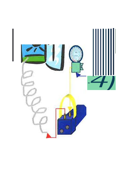
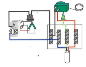
Compressor Electrics

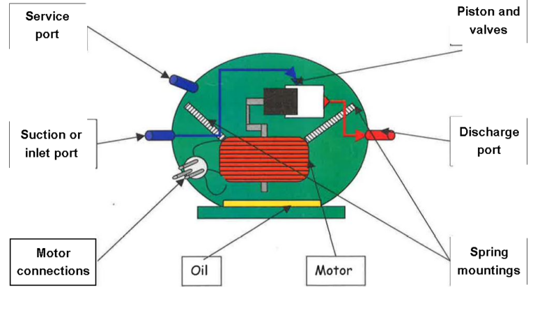
On the side of the compressor there are three pins these are the ends of the motor windings. The motor has start and run windings which are brought together at a common pin.

When the motor is switched on current                                                                    passes

through both windings as the motor starts                                                               to rotate

the start winding is switched off by either a PTC                                                   start device or potential relay.
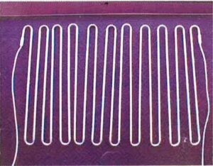
 

Condenser

This is the pipe work on the outside of the cabinet where the refrigerant cools and

turns from a vapour to a liquid. These can be arranged as a fixed grill on the rear of

the cabinet (static), be cooled by a fan or set under the skin.

The pipe from the compressor to the condenser is called the discharge pipe.

Often an extension of the condenser circuit is run around the doorframe to stop

condensation forming, this is known as a door circuit.

Condensers must be kept clear of fluff and dirt to cool the refrigerant efficiently.
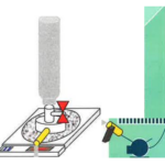
Capillary

This is the very small pipe, which runs between the condenser and the evaporator. The capillary restricts the flow of refrigerant out of the condenser; this allows the high pressure to build up in the condenser and the low pressure to develop in the evaporator. Due to the small diameter of the capillary pipe it can be easily blocked by both dirt and moisture (freezing inside the refrigerant system) so at the start of the capillary a filter/drier is fitted, this cleans and dries the refrigerant before it enters the capillary. It is good practice to change the filter every time the refrigerant system is opened to atmosphere

ptc start relay

A PTC (positive temperature coefficient) switches off the supply to the start winding by using a disc of a material which gets hot as current passes through it and as it gets hot its resistance increases
until there is no longer enough current passing through to run the start winding.

For the motor to start the PTC must be cool

potential relayA potential relay is a mechanical switch, which makes as the motor tries to start, giving a supply to the start winding and opens once the motor is rotating. This is achieved by large start current through a coil, which
magnetic field, which pulls the contacts Once the motor is rotating the current drop and so the field is reduced and the contacts spring apart.

Compressors must be protected against overheating and overloading this is achieved by either an external Klixon (mounted on the outside) or an internal Klixon (mounted inside the compressor body). A Klixon is a simple bimetallic switch, which operates when either the compressor gets too hot or if a small heater inside the Klixon gets too hot, cutting the feed to the motor.

Evaporator

This is the pipe work inside the cabinet where the refrigerant changes from a liquid to a vapour. These pipes can be arranged in many way e.g. pressed into sheets of metal then bonded together to form an icebox (roll bonded), stuck to the rear of the fridge liner so all pipes are hidden (wet wall), etc.

The pipe from the evaporator to the compressor is called the suction pipe. The evaporator must be defrosted regularly to work efficiently.

Domestic frost free appliances became popular in the UK in the early 1990’s. The principle of self defrosting freezers is very simple, instead of manually defrosting the evaporator every 4-6 months the frost free appliance defrosts itself each day.

This is acheived by installing a heater, controlled by a defrost timer, onto the evaporator. The defrost timer must leave the heater on long enough to defrost any ice that has built up on the evaporator but not long enough for the food inside the cabinet to defrost.

Types Of Frost Free Refrigerator Section

Air blown (Parasitel

This type of refrigerator section relies on cold air blown from the freezer section to chill the fridge compartment. The air flow is usually controlled by a sliding vent or baffle operated by a thermostat.

Please note if replacing the thermostat on an air blown appliance that an air thermostat must be fitted (air thermostats sense air temperature and not the evaporator temperature).

Wet wall

This type of refrigerator section works in the same manner as a standard larder refrigerator (ice will form on the rear wall of the liner and then defrost on the off cycle).

Brain Heater

The drain heater is located in the drain channel of the freezer section. It ensures that no ice forms in the drain channel or blocks the drain hole during the defrost period.

brain heaters are usually held in position using adhesive aluminium tape.

brain heater

Thermal Fuse
The thermal fuse protects the interior of the cabinet against heat damage from the defrost heater.

Thermal fuses rupture between +72°C and +84°C. Never leave an appliance working without thermal protection.

thermal fuse

Sensor

The sensor relays the temperature reading from the evaporator to the electronic defrost timer, the defrost timer then determines if a defrost period is required.

sensor

Defrost Timer (Mechanical)

The defrost timer switches between refrigeration mode and defrost mode. A typical cycle is 8hrs ref rigeration/30mins defrost time.

mechanical defrost timer

Defrost Timer (Electronic/PCB)

The electronic timer (PCB) is a more complex version of defrost timer it relies on sensors to initiate and terminate the defrost cycle rather than a set defrost pattern.

defrost timer electronic pcb board

Defrost Heater

The defrost heater can be wrapped around or installed within the coils of the evaporator. It melts any ice that has built up since the previous defrost period.

defrost heater

Rotation Inductor

When replacing a fan motor you must ensure that the fan blade rotates in the same direction as the original fan motor. This can be checked by noting the position of the “Rotation Inductor” on the top of the fan motor and ensuring that the “Rotation Inductor” on the replacement fan motor is on the same side

Electronic Defrost Timer (PCB)

Most electronic timers have a self test mode which can be accessed by referring to the service information handout/Bulletins.

If an appliance which is fitted with an electronic timer is disconnected from the mains supply, when the power is reconnected the timer will check the temperature of the evaporator and determine if a defrost is required (usually colder than -5°C)

Some frost free models that have an electronic display will show a fault code, this will help to identify the problem area. The fault code will be explained in the service information.

All the sensors that are fitted to frost free appliances are NTC (Negative Temperature Coefficient), That means the resistance increases as the sensor temperature decreases.

This chart can be used for both types of sensor, defrost period or refrigeration cycle.

sensor resistance value
door not sealing left open
defrost period too short
Non accumulative mechanical defrost timer