Why use refrigeration?
We use refrigeration to extend the storage times of food, by lowering the temperature we slow down both bacteria and enzyme growth.
How does a fridge cool the food.,
Fridges work by moving heat from the inside of the cabinet to the outside.
So how do they move the heat?
Most modern refrigeration systems work on the same principle, of using a refrigerant that has a very low boiling point (R134a boils at -26°C), and forcing the refrigerant to constantly change state from a liquid to a vapour and back again.
When a liquid evaporates and changes into a vapour
It will absorb heat
When a vapour changes into a liquid
It will give off heat
To force the change in state we change the pressure
Lowering the pressure lowers the boiling point
Raising the pressure raises the boiling point
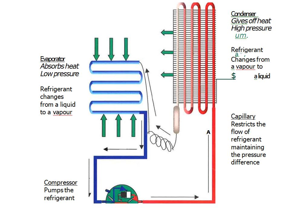
Typical refrigerant system
If the process of increasing and decreasing the pressure or the dissipating and
absorbing of heat are disrupted then the refrigeration process will be affected.
Examples:
– Dirty/blocked condensers stop the heat from being dissipated.
– Iced up evaporators stop heat from being absorbed.
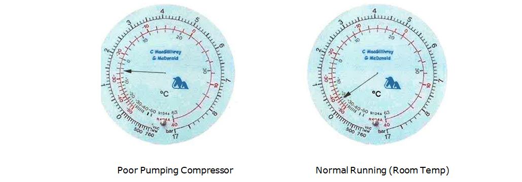
– Poor pumping compressors stop the increase and decrease of the refrigerant pressures.
Main Components
Compressor
The compressor pumps the refrigerant around the system. Inside a compressor there is an electric motor, a piston and a set of valves all of which are hung on springs to cut down vibration and noise. Also inside the compressor is a quantity of oil to keep the moving parts lubricated. This oil is specific to the refrigerant being used in the system and so care must be taken when changing gases and compressors.
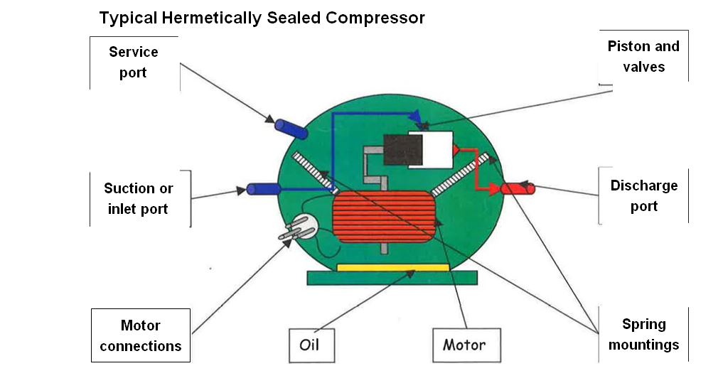
Note some oil used in compressors is hydroscopic (absorbs moisture) and should not be opened to atmosphere for long periods (more than 10 minutes)
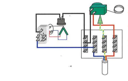
Compressor Electrics
On the side of the compressor there are three pins these are the ends of the motor windings. The motor has start and run windings which are brought together at a common pin.
When the motor is switched on current passes through both windings as the motor starts to rotate the start winding is switched off by either a PTC start device or potential relay.
Condenser
This is the pipe work on the outside of the cabinet where the refrigerant cools and turns from a vapour to a liquid. These can be arranged as a fixed grill on the rear of the cabinet (static), be cooled by a fan or set under the skin. The pipe from the compressor to the condenser is called the discharge pipe. Often an extension of the condenser circuit is run around the doorframe to stop condensation forming, this is known as a door circuit. Condensers must be kept clear of fluff and dirt to cool the refrigerant efficiently.
Capillary
This is the very small pipe, which runs between the condenser and the evaporator. The capillary restricts the flow of refrigerant out of the condenser; this allows the high pressure to build up in the condenser and the low pressure to develop in the evaporator. Due to the small diameter of the capillary pipe it can be easily blocked by both dirt and moisture (freezing inside the refrigerant system) so at the start of the capillary a filter/drier is fitted, this cleans and dries the refrigerant before it enters the capillary. It is good practice to change the filter every time the refrigerant system is opened to atmosphere.
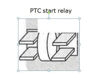
A PTC (positive temperature coefficient) switches off the supply to the start winding by using a disc of a material which gets hot as current passes through it and as it gets hot its resistance increases
until there is no longer enough current passing through to run the start winding.
For the motor to start the PTC must be cool.
Potential Relay
 A potential relay is a mechanical switch, which makes as the motor tries to start, giving a supply to the start winding and opens once the motor is rotating. This is achieved by large start current through a coil, which magnetic field, which pulls the contacts Once the motor is rotating the current drop and so the field is reduced and the contacts spring apart.
Overload and Overheat Protection (Klixon)
Compressors must be protected against overheating and overloading this is achieved by either an external Klixon (mounted on the outside) or an internal Klixon (mounted inside the compressor body). A Klixon is a simple bimetallic switch, which operates when either the compressor gets too hot or if a small heater inside the Klixon gets too hot, cutting the feed to the motor.
Evaporator
This is the pipe work inside the cabinet where the refrigerant changes from a liquid to a vapour. These pipes can be arranged in many way e.g. pressed into sheets of metal then bonded together to form an icebox (roll bonded), stuck to the rear of the fridge liner so all pipes are hidden (wet wall), etc.
The pipe from the evaporator to the compressor is called the suction pipe. The evaporator must be defrosted regularly to work efficiently.
R600A Refrigeration

Removal Of R600a From An Appliance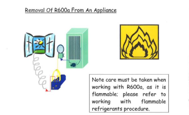
• Check the area is safe to work in.
• Access the system (piercing pliers, line tap, schrieder, etc.)
• Connect up as shown (ensure vent hose goes to clear air)
• Run the vacuum pump with the tap on the gauge open
• Keep running the vacuum pump until all refrigerant has been removed
• Check, both sides of the system (pierce in to high side)
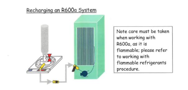
- After full evacuation of the system (20mins)
- Disconnect the gauge line from schraeder valve
- Purge the R600a charge line to clear air (eg,outside) not within working environment
- Ensure the gauge line tap is closed then connect to the system
- Place R600a gas bottle on the scales and secure charge line
- Reset the charging scales display to zero
- Open gauge line tap and scales will count down from zero (minus figures)
- Stop when 95% of full charge has been added if carrying out a re-gas
- Stop when 100% of full charge added if compressor changed
- Disconnect and purge charge line to clear air (eg,outside)
- Run and test
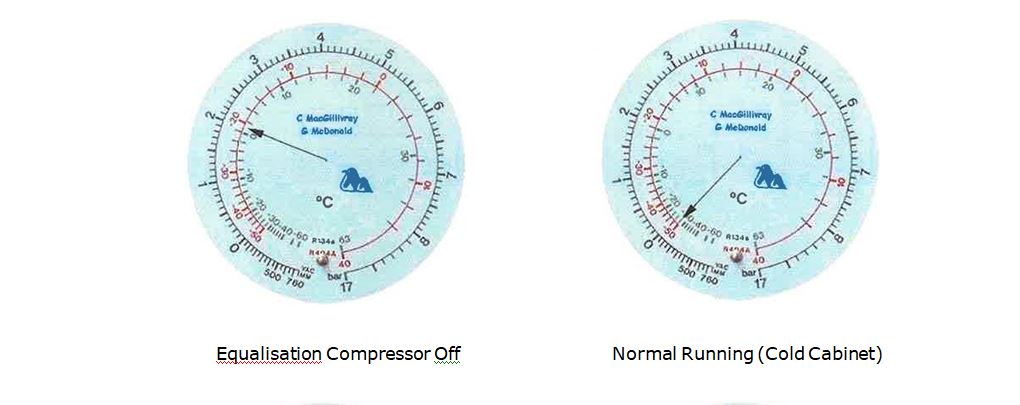
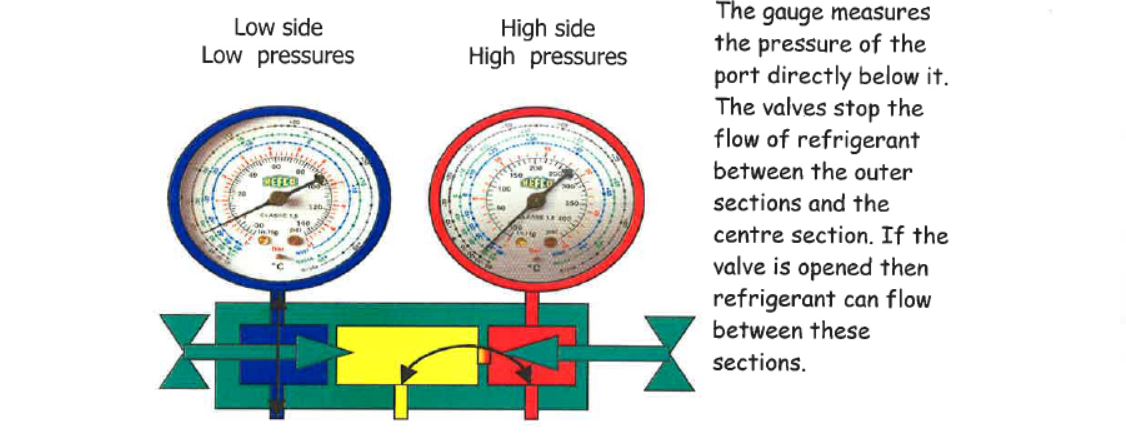
Refrigeration Gauges and Manifold
Understanding the gauges and the pressures shown on them is essential to correctly diagnose and repair a refrigeration system.
The gauges indicate the pressure inside the system. The manifold allows you to add and remove refrigerant from the system and is simply a set of valves and interconnecting pipes.
HFC (R134a, R404a, etc.), CFC (R12, etc), HCFC (R22) Recovery
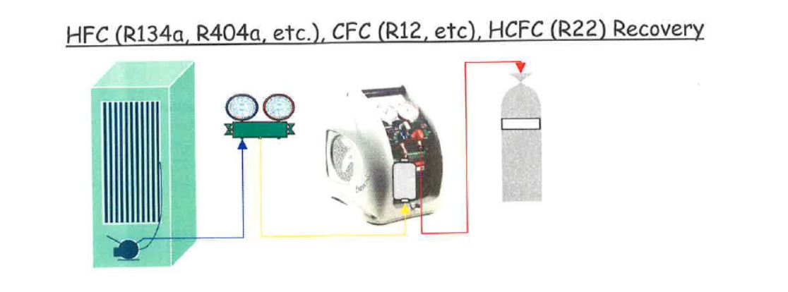
- Asses the refrigerant type
- Access the refrigerant system (piercing pliers, line tap valve, schreider valve, etc.)
- Connect recovery unit to correct recovery cylinder as shown
- Recovery refrigerant (staying below Zero)
- Check both sides of system are empty (pierce the high side)
- Purge unit before storing
Evacuating A System

Refrigerant systems need to be evacuated to remove air and moisture after service work has been carried out. Moisture will only be removed if a full vacuum is held for a prolonged period of time (20 minutes).
The pressure gauge should indicate 28″Hg and this reading should be held when the manifold is closed and the vacuum pump switched off. If the pressure reading rises then this would indicate that the system has a leak.
Moisture held within the air left in a refrigerant circuit can effect performance and possibly form acids that will damage the system.
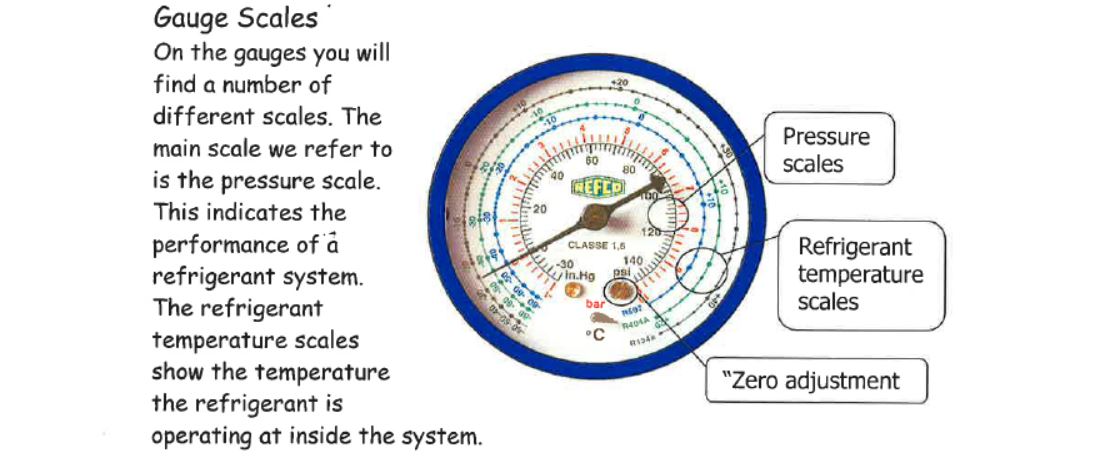
Pressure Scales
There are two main scales commonly used to measure pressure. Pounds per square inch (psi) an imperial measurement which is being replaced by bar. Which is a metric scale for pressure measurement. 1 bar is equal to 14.7 p.s.i. Zero on both scales is atmospheric pressure. Any pressure below atmospheric pressure is referred to as a vacuum, in bar readings a vacuum is indicated by a minus sign before the number and on the p.s.i. scale a vacuum is measured in inches of mercury (“Hg). Some newer gauges may also show a vacuum in millimetres of mercury (mmHg). The Mercury in these measurements refers to the size of the column of Mercury that can be sucked up a tube by this amount of vacuum.
p.s.i x 0.07 = bar
bar x 14.7 = p.s.i.
It is important to always check that your gauges are reading zero before connecting to any system. If your gauges read 5psi when open to atmosphere then 5psi would have to be added to the pressure reading taken from the system. Also before connecting to any system ensure that the valves are closed.
Recovery Cylinder Colour Codes
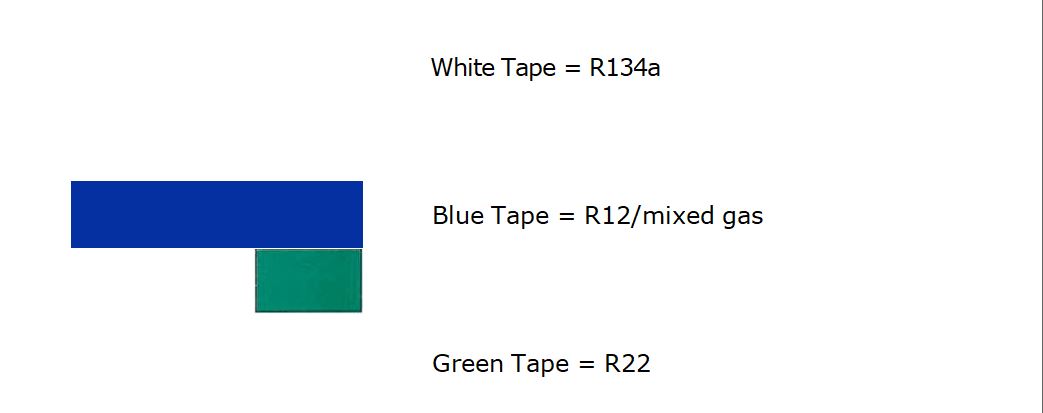
Never mix refrigerants in the R134a and R22 cylinders R12 Cylinder can have any gas other than R134a & R22Never overfill. or over pressurise recovery cylinders
Typical System Faults
| Fault | Symptoms | Gauge | Repair | |
| Com p. Running |
Com p. Off |
|||
| Short or under charged with refrigerant | Only partly frozen evaporator Cool condenser Running continuous (possible) | Lower thanexpected |
Rises when switched off | Leak test. Remove refrigerant. Repair leak. Change drier Vac. System Recharge System
Leak test |
| Over charged | Fully frozen evaporator Suction
pipe frozen outside cabinet Running continuously Comp. Very hot |
Higher than
expected |
Higher than expected | Remove refrigerant (vent or recover as appropriate) till frost line goes inside cabinet
Leak test |
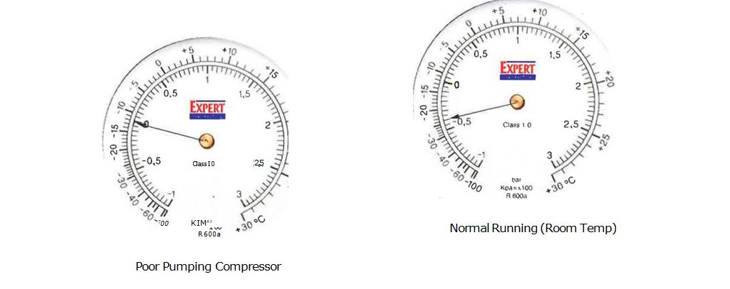
| Poor pumping
compressor . |
Partially frozen evaporator Noisy compressor Running continuously Comp. Very hot | Much higher than expected | Rises very quickly (refrigerant can be heard passing back through comp.) | Recover/vent refrigerant. Change compressor and filter. Vac. System Recharge system
Leak test Run test |
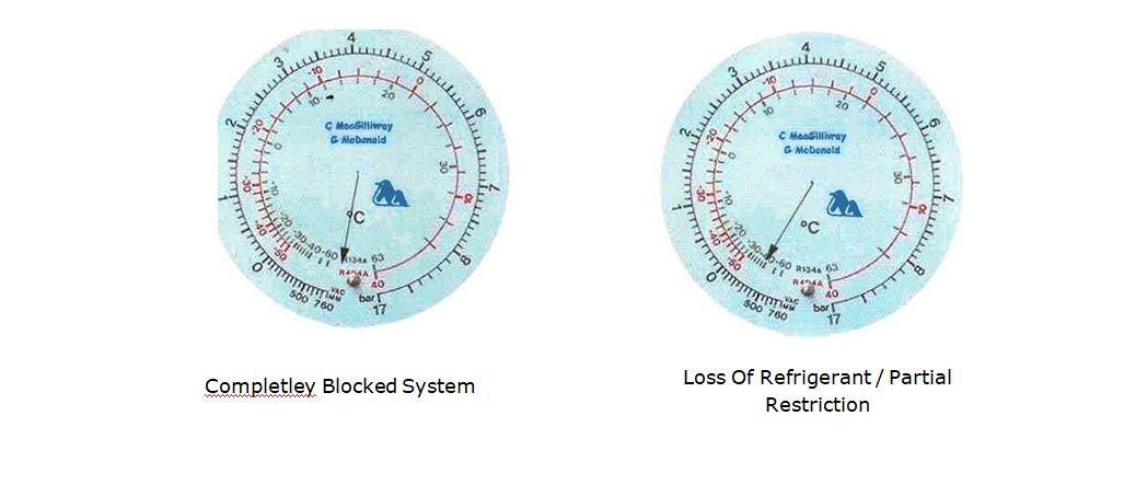
| Restricted/partially blocked | Partially frozen evaporator | Lower than
expected |
Rises very slowly | Recovery/vent refrigerant. Clear blockage |
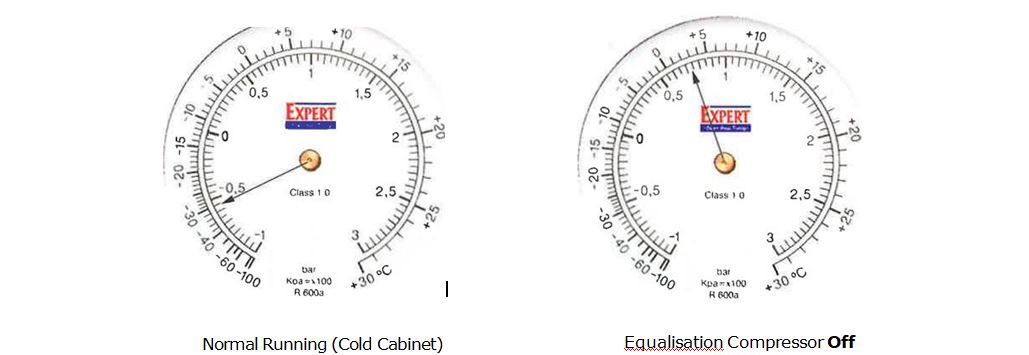
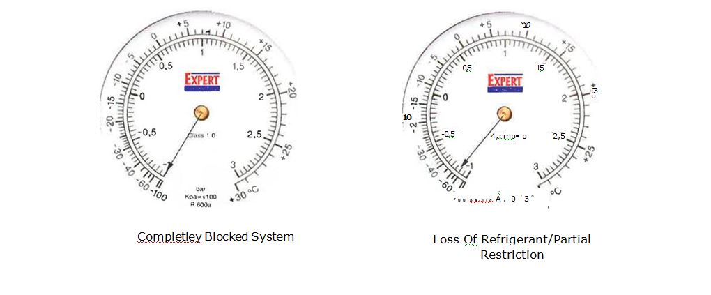
R600a Typical Gauge Readings
R134a Typical Gauge Readings